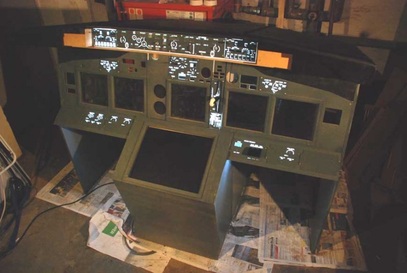
The cockpit has been moved from the basement into the cockpit room. You can see the current status on one of the pictures. At the moment i do a lot of work to fill out the empty places in the MIP. This needs a lot of time. When this work is finished i will take care about the throttle quadrant.
One interessting aspect maybe: I managed to get the FMC running on my android galaxy tab using the iview app. But it runs very unstable and the response is not satisfying. Maybe a new software update has fixed these problems – i did not check.
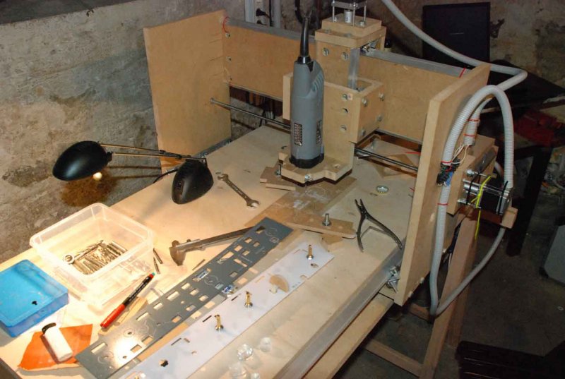
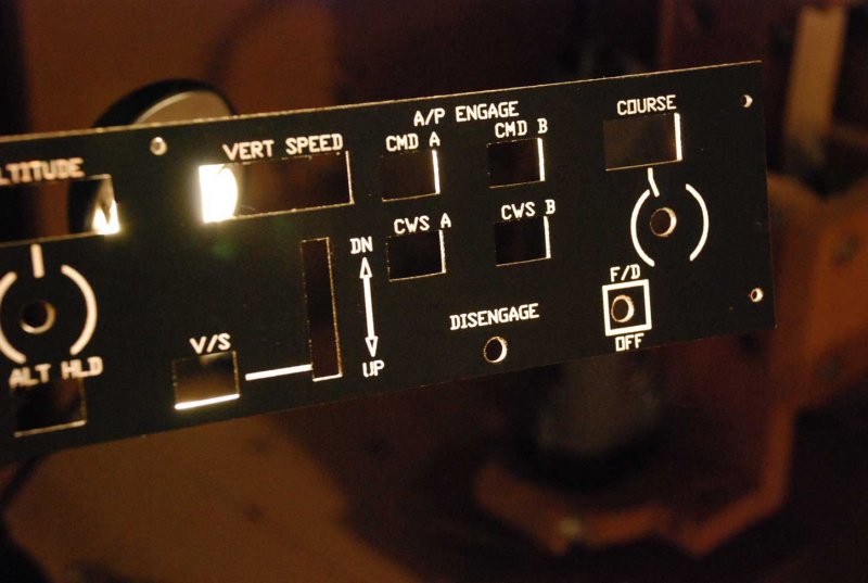
I managed to buy a new CNC router (Moederl) which is far better than my old diy router. Now i am able to do my pieces in much shorter time because i can run at higher feedrates. You can see the AFDS panel and also (yiep yiep) the first homebuilt pcb board for it. I also can mill aluminum now. This will be handy when it comes to a new gear lever.
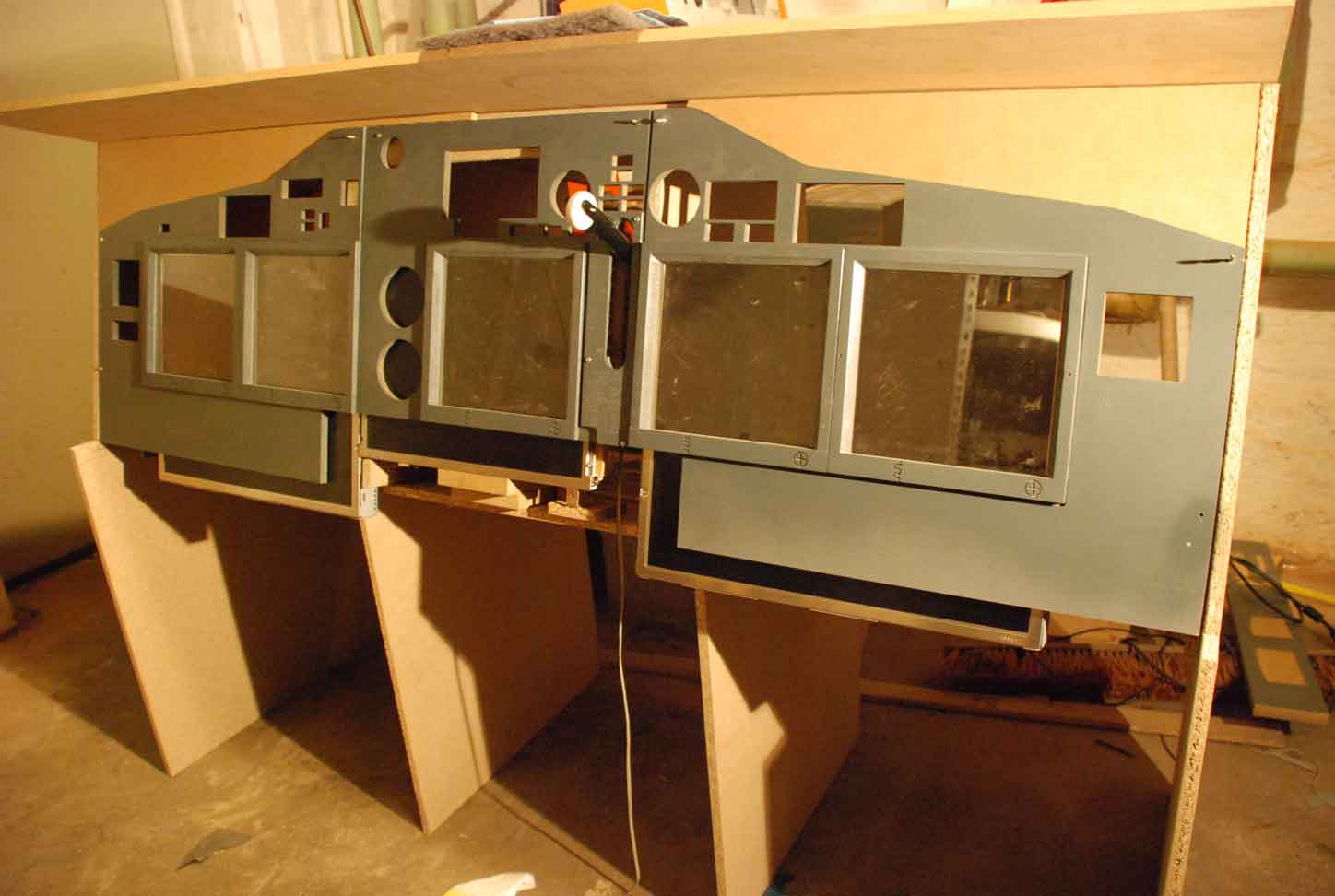
Having a cnc router gives you the problem that you really need to spend a lot of time for planning the parts. My workflow is the following: The autocad dwg drawing is the source of all information -> panel export as dxf for Cut2d cam software -> in cut2d i plan the tool paths and create the nc code -> export to Mach3 Software which drives the router.
Recently i started to plan the panels in 3D with Audodesk inventor. This increases the ammount of planning time dramatically but i can be sure that the parts will fit together and i do not have problems in during assembly.
Overall, i am quite satisfied with my current cockpit but i see 3 major issues which cause headache for me. 1. The encoders used in the MCP have the known problem that the BU card does not read the signal fast enough so when i turn the encoders, the BU cards misses some detents. This problem is known but i didn´t get a good solution yet. I will make a new MCP and can solve this problem then using a LUA program or using alps encoders which simulated a turn of the know. 2. The MIP is not made out of PDF but out of some weaker material (MDF was oput in the shop when i bought the material so i choose other material calles pressspanplatte. Now i am not satisfied with the stability but i do not want to make everything new. 3. The room where the cockpits is installed is too small for 3 projectors and an enclosure : (((.
A last thing, when i ordered electronic equipment here in germany, i found out that reichelt has some good knobs which are not as expensive as the OC stuff… check this linkhttp://www.reichelt.de/Drehimpulsgeb…6ef5c099aa99ee
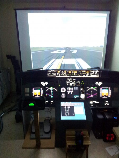
Cokcpit has moved into its new room. Visualization with 1x projector.
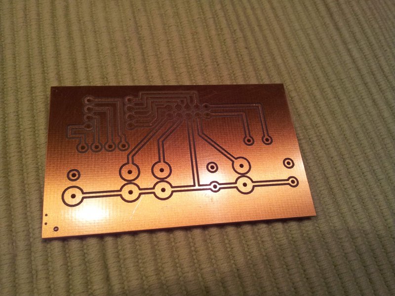
First PCB Board fresh out of the home production