
Of course when you do have your first MCP you are very happy. But as the time goes by you find more and more things which are are not satisfying. As you can see in an older post, the MCP Ver 1 was based on a piece of MDF material for stabilization. The LEDs for the mode selection have not been placed on the push buttons but above or next to them. No FLT intv or SPD intv buttoms were available. But the thing which was most annoying was the way the cables have been organized. Totally chaotic and a lot of hot glue was applied to provide some stability for the soldering points.
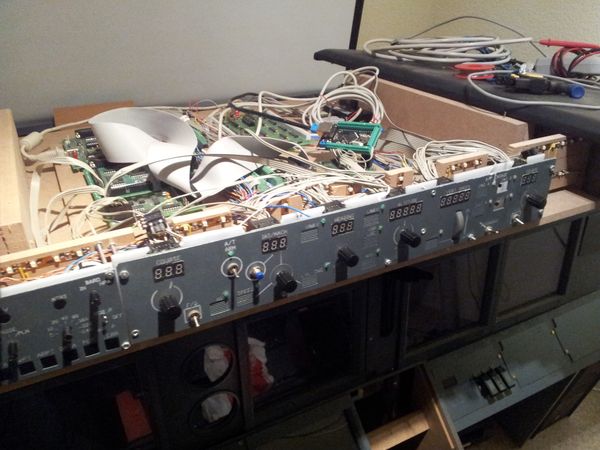
Cable Chaos behind MCPV1 – what a mess !
So it was time to think about a new MCP. The first planning was done with Autocad Inventor. From earlier panels (COM, NAV etc.) the 7 digit Led displays, encoders and push buttons were already available in the object library. The after some days of planning the final Layout was clear.
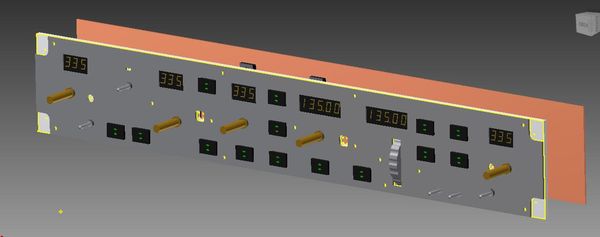
Final Layout of the MCP Panel.
It was also the first time that i used 3D modelling to create parts as i needed them. In this case the holder and the Vert Speed Dial have been designed based on the surrounding parts. You can see the details below:
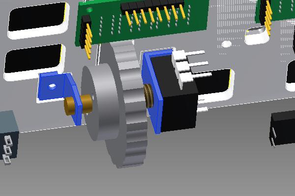
Detail View of the Vert Speed Dial and the Holders.
The different parts of the inventor file have been exported to Autocad format. Audtocad was used to do the fine work on the different layers (front, aluminium back, PCB drill holes…) expecially the cutouts for the Buttons, LED Displays and so on. You can see the Autocad File below. I also made a small layout of the Pokeys card. The card is attaches to a separate holder on the back of the panel.
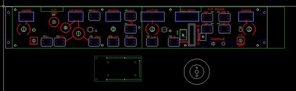
Autocad File with the different layers of the panel. You also can see the rought layout of the Pokeys Card.
Based on the Autocad Layout – i now know the position of the drilling holes for all the contact pins for the LED display, switches, buttons etc. The positions of the drilling holes is transferd into a new Sprint layout for the final PCB board. The Layout of the PCB board was done with the program “Sprint Layout” from the Abacom Company. You can see the layout of one (of the two) PCB boards used for this MCP project.

Sprint Layout for PCB (1/2)
Then the CNC Mill is turned on and two weeks later all parts are ready for assembly. You can see the “physical” Bill of Material placed on my kitchen table.
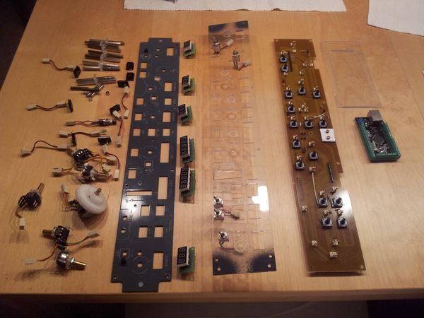
All components needed for the new MCP have been placed on my kitchen table before the assembly process
The MCP has been assembled and all components are connected. Basically it is a 2 layered MCP. Front Layer includes: 7 Segment LED, Encoders, Buttons, Switches. The back layer includes the PCB and the Push micro switches. If you press a button in front – the impulse is transfered to the micro switch on the PCB at the back with a wooden stick. You can see it in the picture. (CMD A/ B on the upper right). You can see the switch in the front and the wooden stick connected to the mirco switch in the back. This solution was done by Manolo Hernández-Peña Marcellán and inspired me for my project.
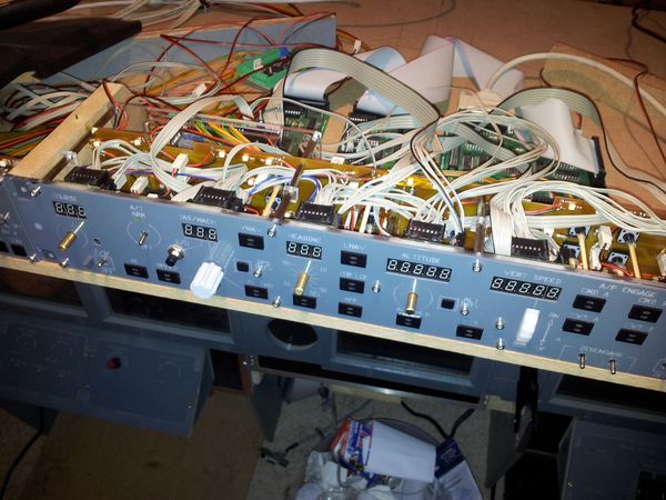
Front View of the new MCP Version2.
Very interesting. May I have a copy of complete wiring diagram as well as pcb of your display MCP.
Thank you and warm regards,
Herly
sorry – i can provide the sprint layout file if you want. just send email…
hi, sir
can i give me file mcp for engraving backlight and 3d print
Okay then please inform your email..
Herly
Hi please help me to purchase MCP boeing 737 EL parts
i_ Retary Encoder
ii_ VERT Encoder (Wheel Rotary encoder)
iii_ Pushbutton legend back light
Hi Andreas,
The MCP panel looks very nice. Did you engrave it with a CNC using engraving bit or laser diode? If the bit was used, could you share what type of bit and what depth/feed?
You build looks awesome.
Regards – Seb.
I use 0.5 mm end mill for the engraving. I do not have a laser (unfortunately).
The depth is set to 0.3mm, federate is approx 120mm / min.
Usually I apply 2 layers of color to get the light blocking effect. And it takes 2 weeks drying time before I can engrave it. If the color is not fully hardened, the engraving looks sh**t.
does anyone have cad drawings for overhead panel as i have just built a cnc 1500×1200 x300 and as yet have no idea how to create any panels cheers if you can email them to trafficmanagment1@gmail.com
Hi ! I like your work very nice. I want to make one but I dont know how. Can you send me the instructions ? Thank you very much.
can you please send me sprint layout file as I like this and willing to make one. my email….
thanks
Hi can you send me the files to my email address mate
Sebastiano123@op.pl
?????
Hi
i need CNC file for MCP 737 and autocad
could you share _?
isurek_2006@hotmail.com
nice job.
can u give me plan drawing mcp panel
which ic did you use max7219 or shift register for 7 segment display?
Hi, can you please send me the cad file for the MCP? Thanks
What size seven segment displays did you use? I can’t seem to find a correctly scaled mcp dwg. It seems like all of them have the correct overall dimensions but the holes for the screens and encoders are way to small to fit any encoders or screens i can find
I’m very interested in what switches and caps you have used. If you are making your won caps have you got any design and manufacturing information?
Nice project
Can i have wiring diagram as well as pcb of your display MCP.
Thank you and warm regards,
Hello,
Could you please share the MCP’s DWG files.
Regards