
Details about my Gear Lever which i designed new from scratch.
First the drawing which explains the Basic parts: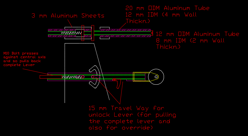
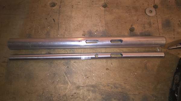
First parts have been the two shafts. The Inner Shaft is necessary for the lock override function and also holds the spring for pulling back the gear Lever. I ordered alu tubes which have just the right Diameters to insert the inner into the outer shaft. ▼
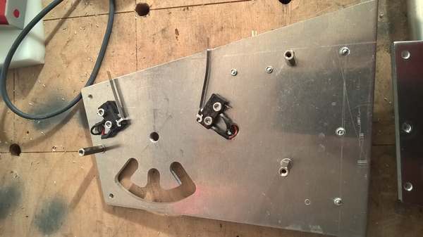
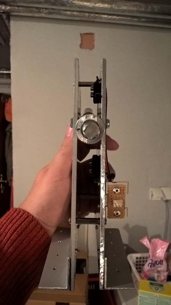
The next parts are the side walls. These are made out of 3 mm Aluminum Sheets and have been cut to the right dimensions in my mitre saw. (Metabo ; ). The cutouts for the lock positions have been done on the CNC machine. The Position of the cutout and the angles (UP – OFF – DOWN) are adjusted to my Simulator but i geuss this will fit in most Cockpits… For getting the Signal to the Simulator i put in 2 micro end Switchen in the correct positions. So when moving the Lever to the UP or DOSn Position, the related Switch is triggered. ▼
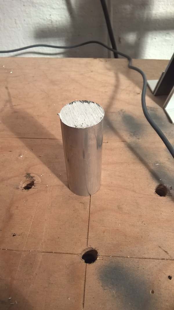
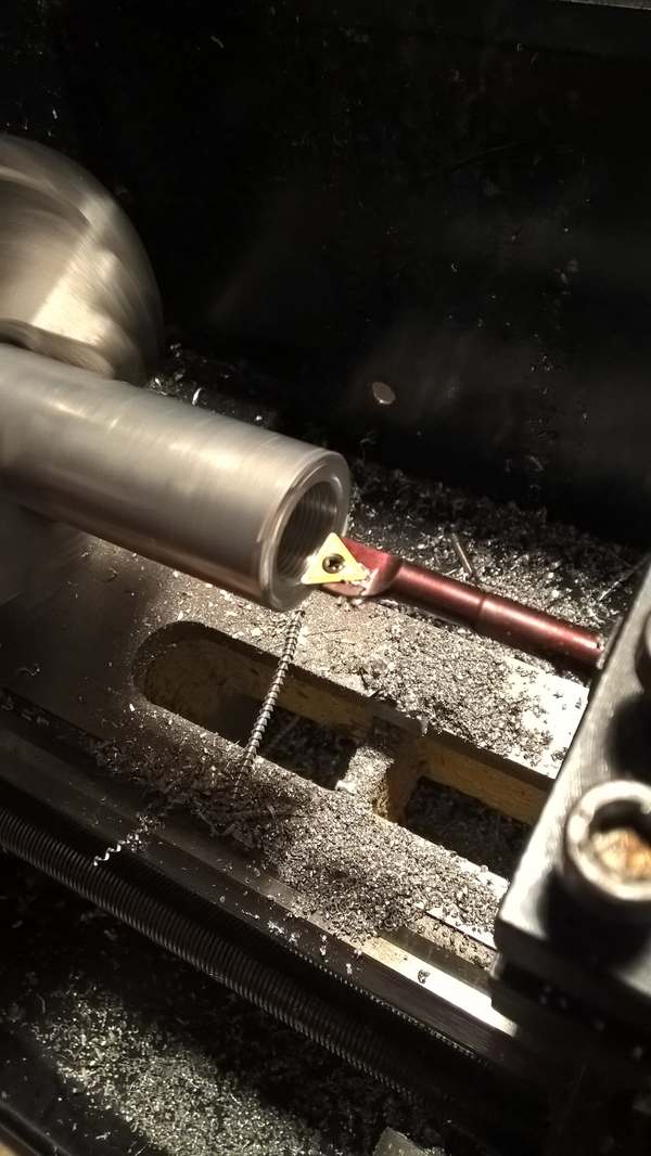
The most complex and time consuming part was the holder for Plastic Wheel. I used a solid bar of Aluminium and turned out the inner Diameter so that the parts fits on the outer shaft.▼
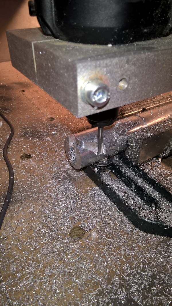
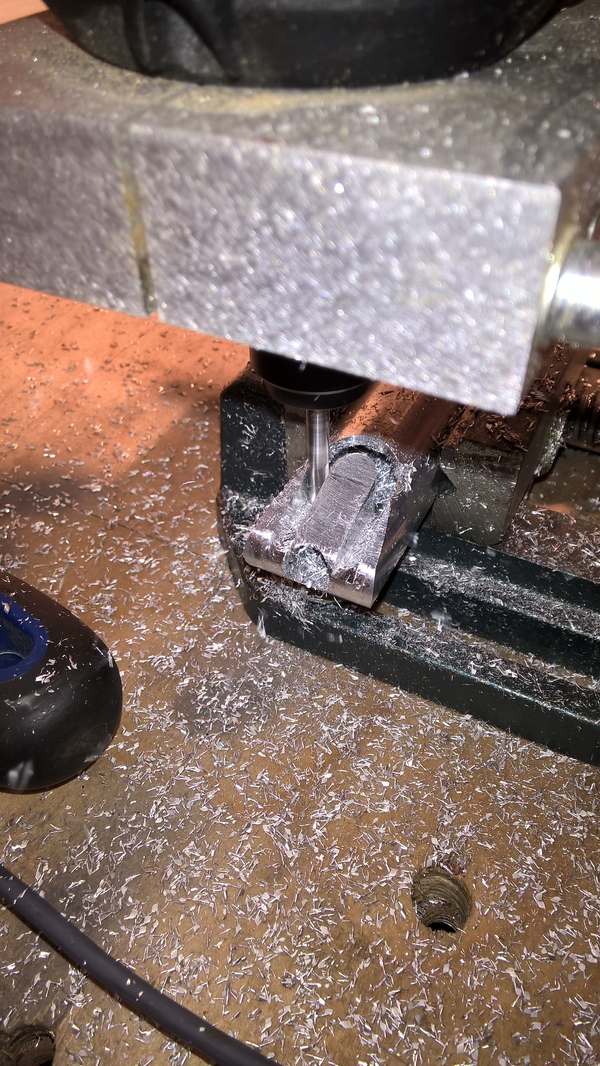
Then the CNC is used again to mill the cutout for the wheel ▼
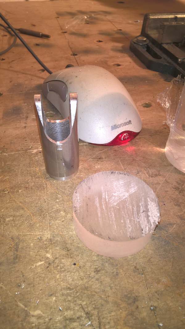
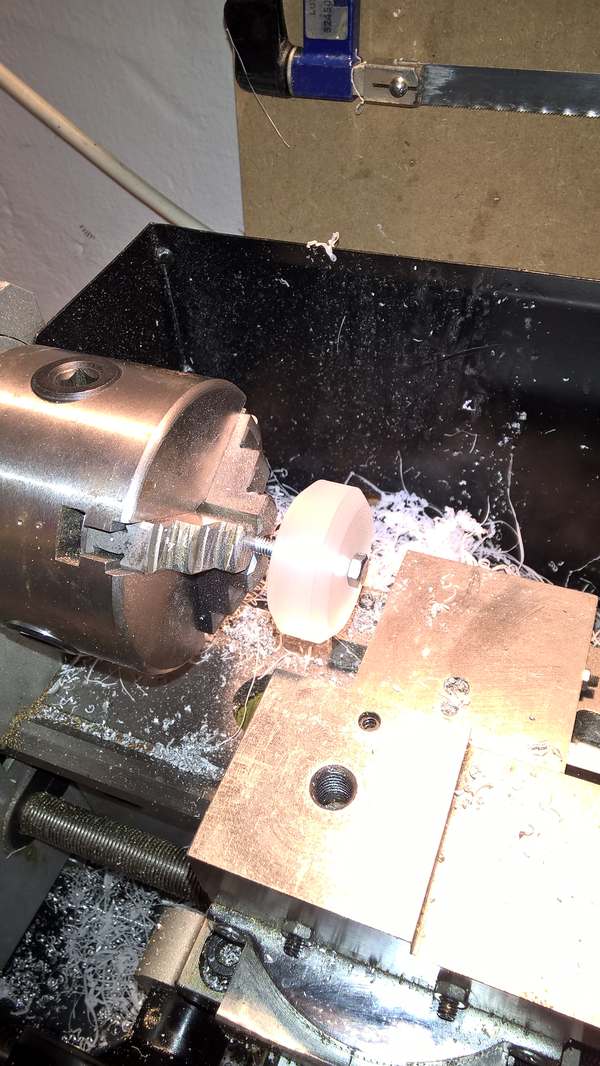
The wheel is made out of a solid bar of clear Acryl and brought into the correct shape on the lathe ▼
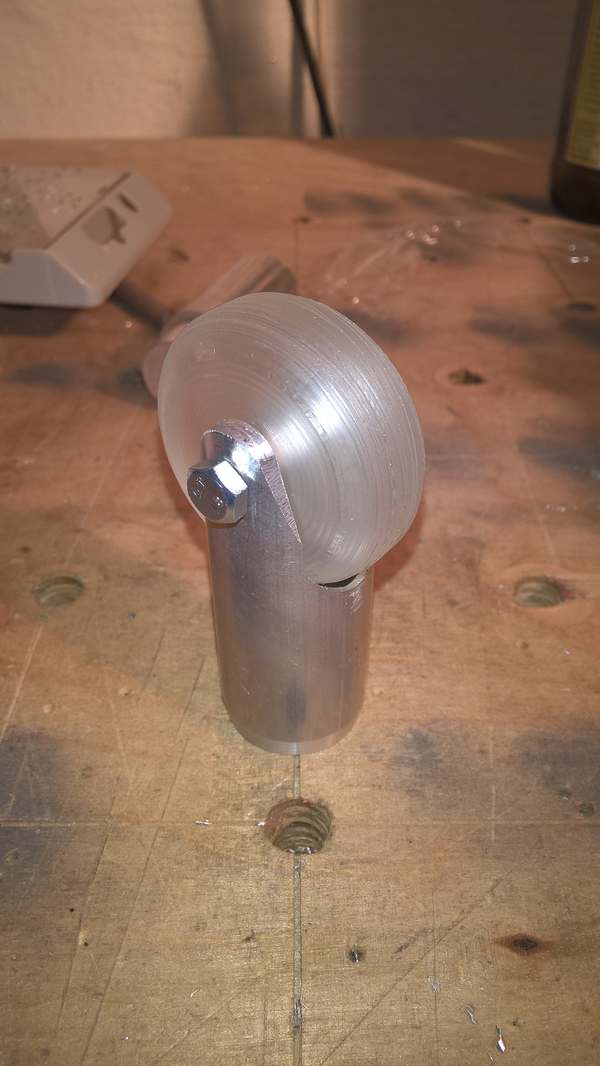
And assembled ▼
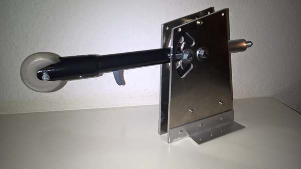
Finally all parts come together and make a nice DIY Gear Lever. What you cannot see on the Pictures is the small red Trigger for the override function. The Trigger is fixed to the inner shaft and works very nice.
A summary of the Lever and how it works can be found on my Youtube channel:
And please subscribe. Thats the least thing you can do for me….
END OF GEAR LEVER SECTION 05.10.2016