
The Overhead Panel was purchased before Christmas and arrived 4 weeks later. I installed all switches, rotaries and fake gauges. When this was finished i realized that i might have a lot of gaps between the the switches and the holes. The first picture illustrates that problem. So i had to disassemble the complete hardware again and masked all switch holes. It took me 2 hours to disassemble and mask it.2 Hours waste time if i had done everything right the first time.
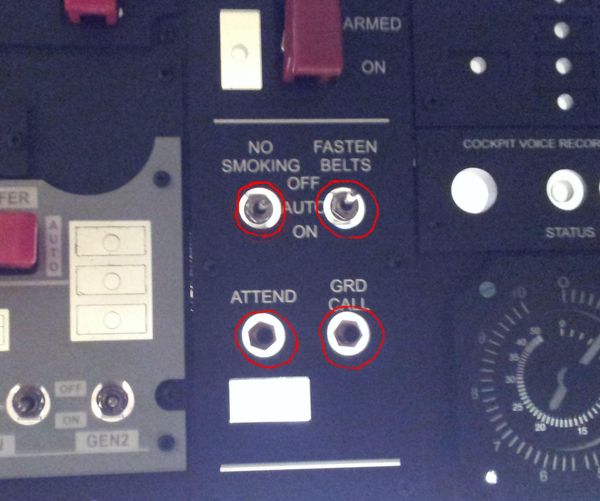
Gaps between the switches. Backlight shines though.
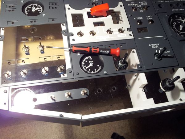
Disassembling the Front Panels again
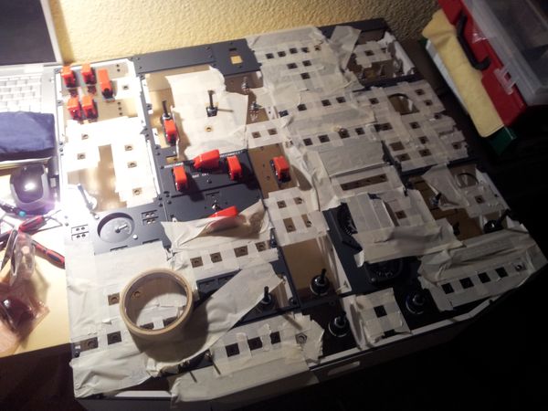
All holes have been masked and are ready for painting.


