
Hello,
on this page -i´d like to show you the pictures of the original B737-300 TQ conversion. This page will be updated regularly as the TQ conversion project will progress.
Start
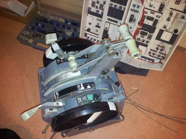
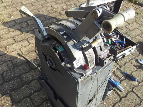
This is the TQ as it arrived in April 2013 at my house.The TQ was bought at www.oncealoft.com and shipped with FedEx. Before starting the conversion i need to put it apart.
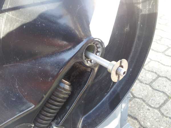
The inner shaft is securing the trim wheels.
The trim wheels have been removed.
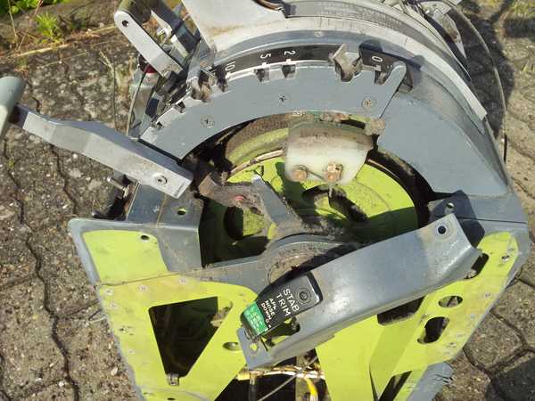
Side walls and Trim Lightplate have been detached.
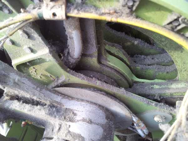
There is a lot of dust and dirt inside. I used a toothbrush to clean it out. Better idea would be to use pressured air but i do not have a compessor.

This shows how the trim indicator is connected to the Servos motor.
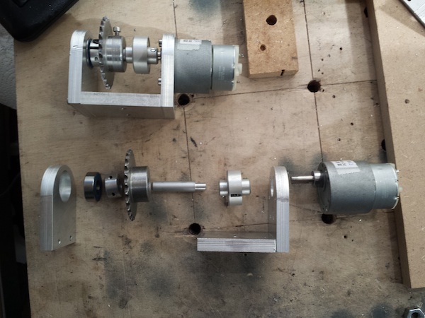
The Motorization for the Throttle Levers is provided by 12V DC motors. The have a small gearbox and turn with 15 rpm. A simple slip clutch is mounted on the motor shaft. The slip clutch prevents damage to the motorization system and enables manual movement of the levers while the motors are powered. The coupler connects the 6mm shaft with the 8mm shaft used for the spur gear. The coupler is the weakest point and i have to replace it as soon as possible. It tends to bend a little bit when the sprocket chain is under tension.
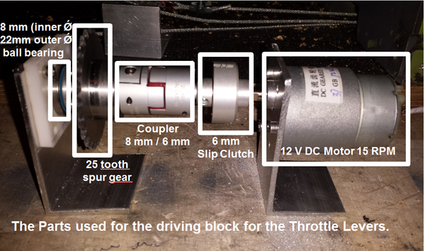
Here you can see the parts used to make the driveing assembly. The slip clutch is needed for manual operation of the throttle levers.
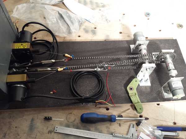
Below you can find a picture of the complete unit which drives the Throttle Levers. I need to improve the Holders for the DC Motors also. For the position measurement of the Throttle Levers, i purchased draw wire potentiometer. These units are basically a multiturn potentiometer (Bourns) and a spring loaded return mechanism. if you move the levers the movement is transfered with steel cable and sprocket chain. The draw wire if the potentiomenter is attached to the sprocket chain. If you move the lever, the wire is pulled out and the potentiometer give out the changed resistance. If you move the lever to other direction, the wire is pulled back inside.
You can have a look at the youtube video i made which shows the mechanism.
Before i bought the draw wire sensors, i considered also other solution to pick up the position of the levers. But finally this is the most simple and reliable solution. But it is expensive. If you want to buy it in Europe or America you´ll probably have to calculate 170 € per piece !!! So i checked and found a company in China which sells a sensor for 100 €. The Company is called Qiqi and can be reached via this link. And don´t worry – they speak english… You might want to ask for a CWP-S250 (250mm wire length). Make sure to tell them that you need resistance as output and not voltage. I ordered the wrong ones with voltage output. But that kind of signal cannot be read by Bodnar Card or OC cards. In the end i opened the sensors and removed a PCB which produced the voltage signal.
Motorization of Throttle Levers and Draw Wire Potentiometer
For the motorization of the TQ, you probably need to renew the 2,5mm steel wire which is used by Boeing in the Throttles. I strongly suggest to use 2,5 mm steel cables WITHOUT plastic coating. I used these coated cables before and it somehow created unnecessary friction during Lever Movement.
The steel cable is fixed to the Throttle Lever “Wheels” with a steel ball soldered or welded onto the steel cable. I tried to remove the steel ball from the original cables and use them on the new ones but i did not succeed removing them. So instead i used a M3 nut. The steel cable is inserted into the nut and with a vice/vise/Schraubstock i deformed the nut. Now it is pressed tightly onto the cable. A small wire is securing the nut in the gap of the wheel.
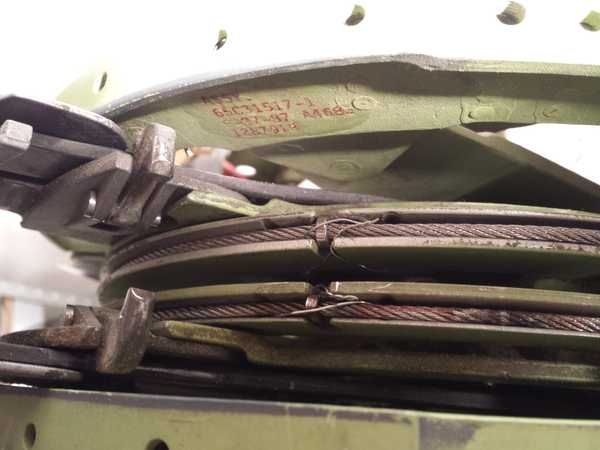
M3 nut keeps steel cable in place
After i was not very satisfied with the old holders for the DC motors i made them new. The tension on the sprocket chain was bending the motor assembly. The new design is much better and stronger Below is a picture of the old and the new design. The components like the clutch or the bearing is the same – but the holder is made from aluminum and very sturdy.
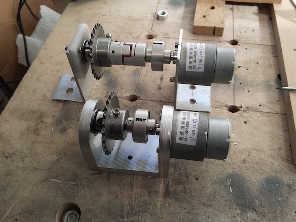
A comparison between the old and the new holders for the motors
The new holders and the components
Last update 29/04/2014
A very interesting method to drive the thrust levers – excellent idea
Hi,
Do you still have the PCB layout for the FMC?
I cannot seem to find any ready ones on the internet so I might have to build this myself like what you did.
Thanks.
Hi! Andy
can you give me the link for shop online for accessories (tooth spur gear, coupler, slip clutch etc..
thank you
rakouth
All the gears etc. are bought at maedler.de
Exept the geardrive for the trim wheels – you need to order in America, they have a different system (other modul for tooth wheels)
hello
I purchased DC MTOTO PLUS
Cannot connect to prosim using the throttle script,
Can you give a script